
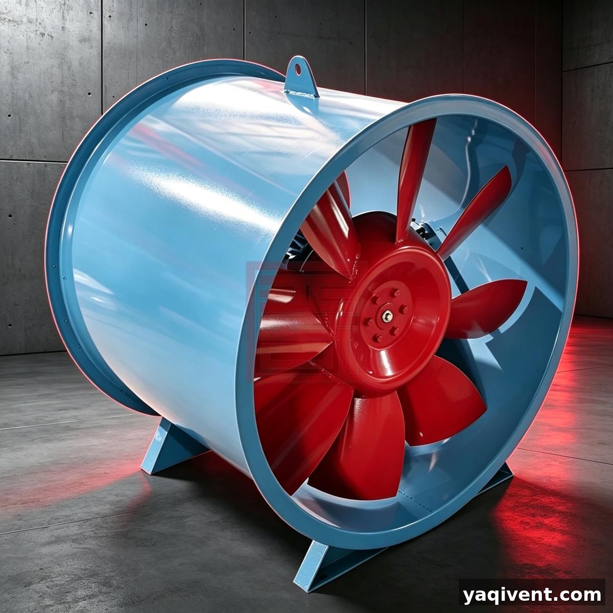
1. Overview of SWF Mixed‑flow Fan
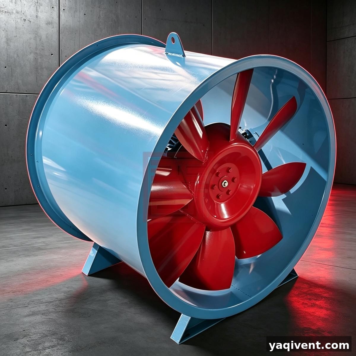
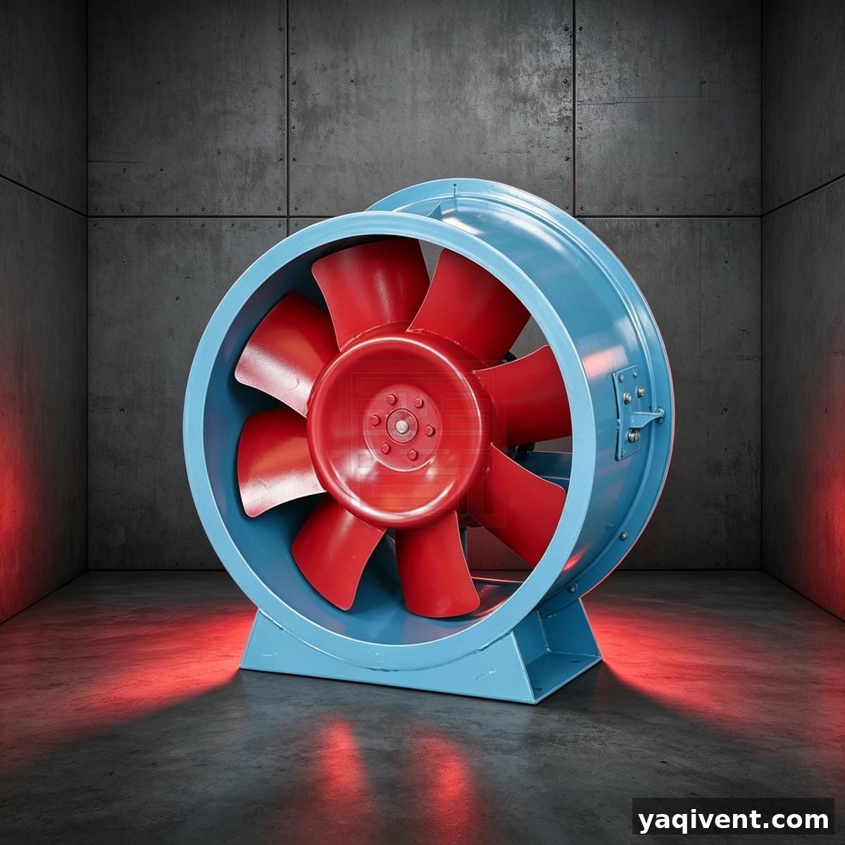
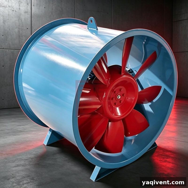
1.1 The SWF mixed‑flow fan is designed with meridian‑plane acceleration technology. Its impeller hub is conical, and a conical inlet nozzle is fitted at the fan inlet. Airflow discharges in an inclined direction, combining the characteristics of both axial‑flow and centrifugal fans. It effectively reduces external flow noise; under conditions of unit air volume and unit total pressure, the A‑weighted sound level can be reduced by 2‑dB(A). High fan pressure can be achieved at relatively low rotating speeds, making it a viable replacement for low‑pressure centrifugal fans.
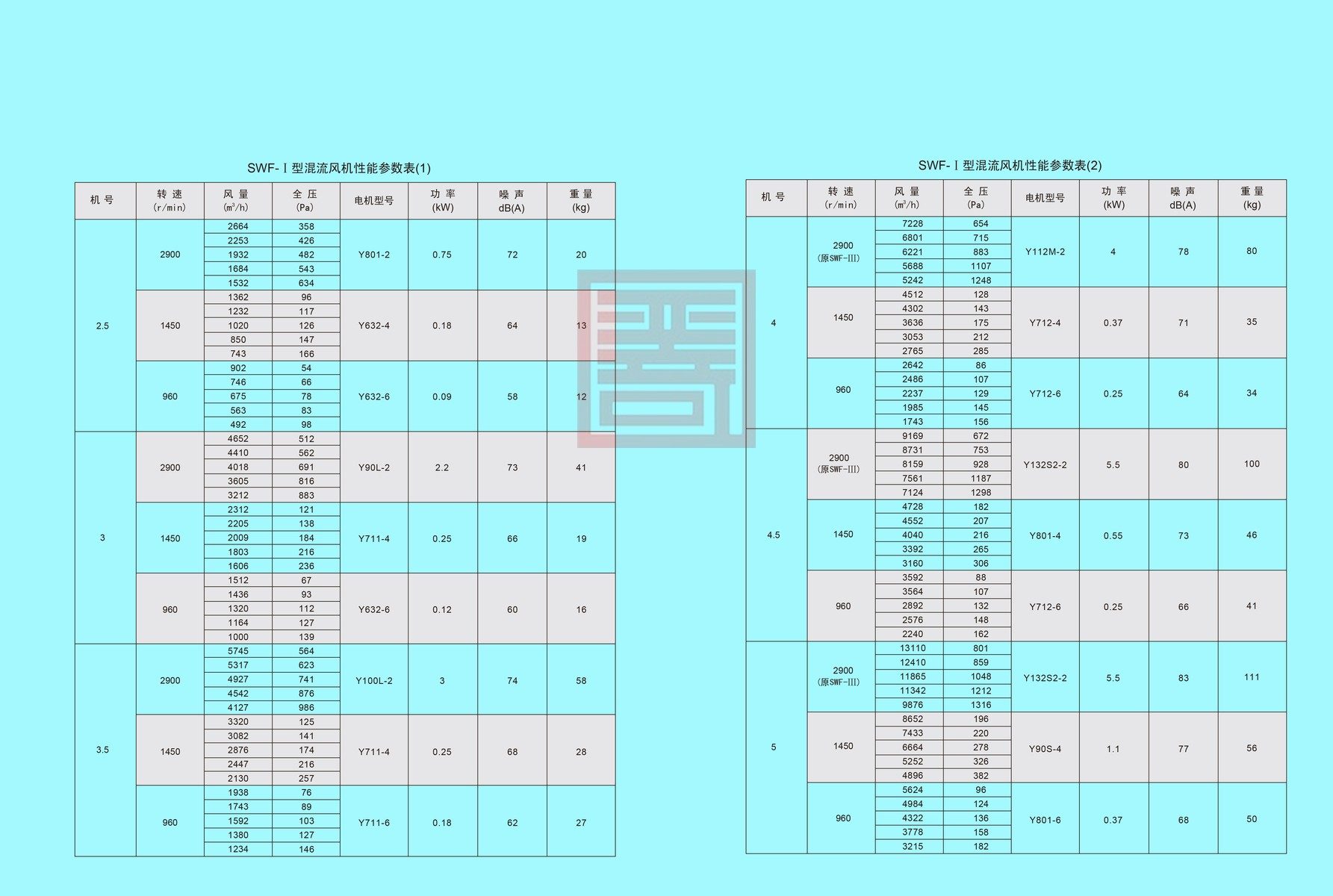
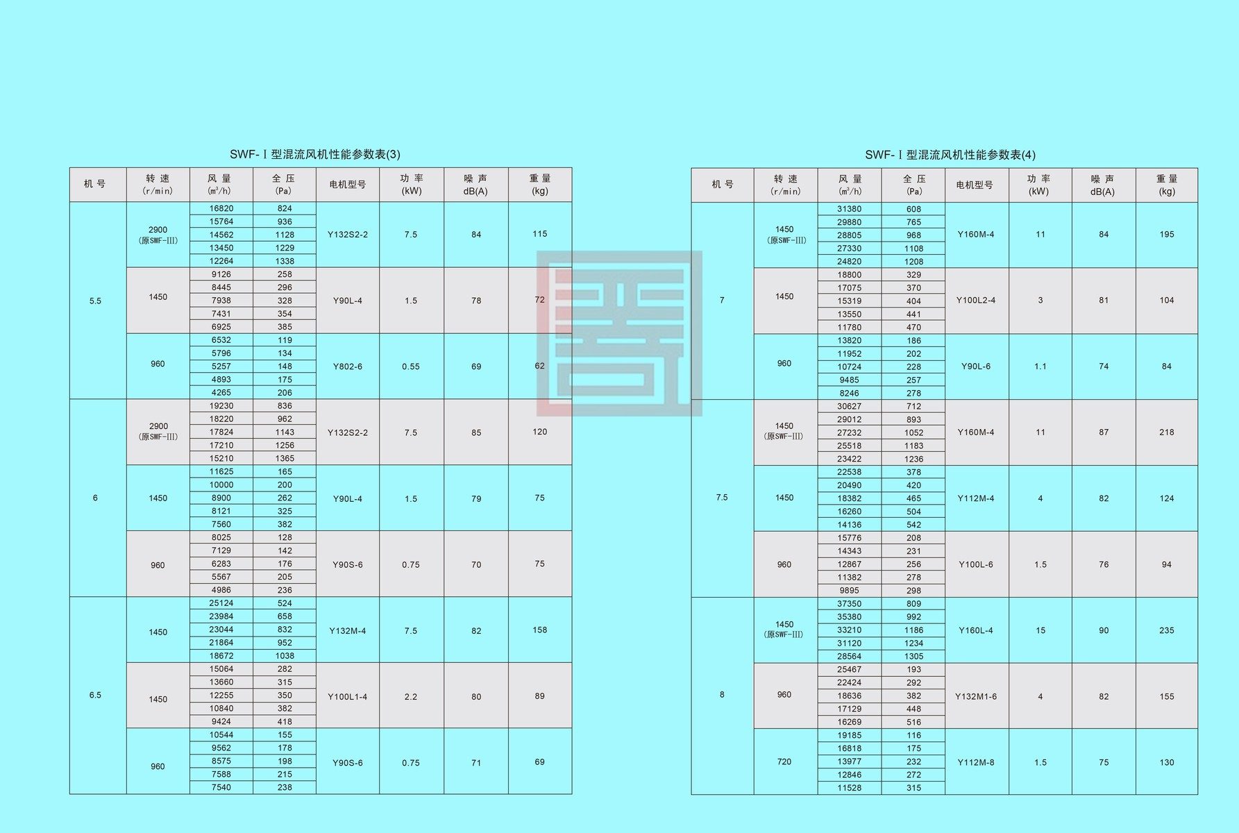
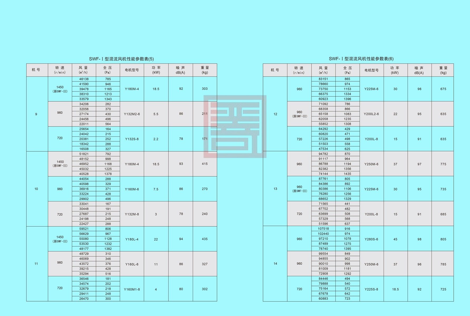
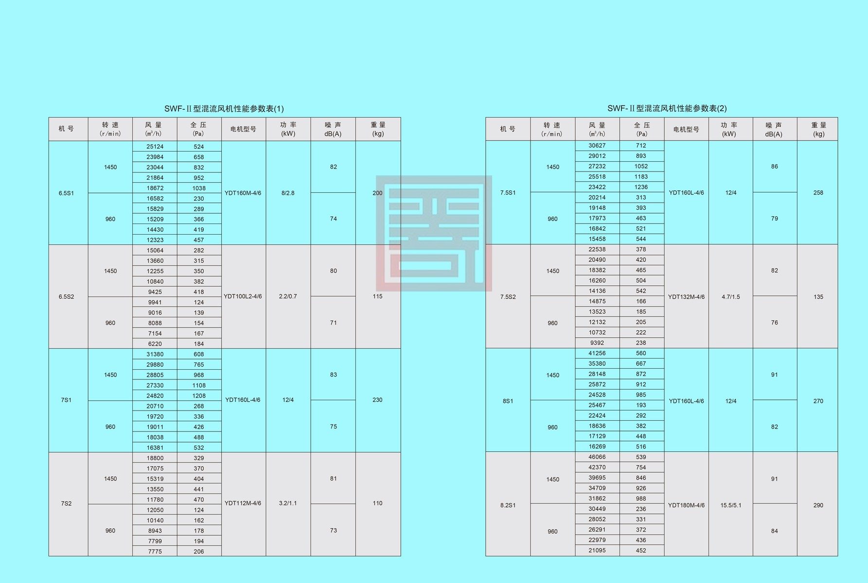
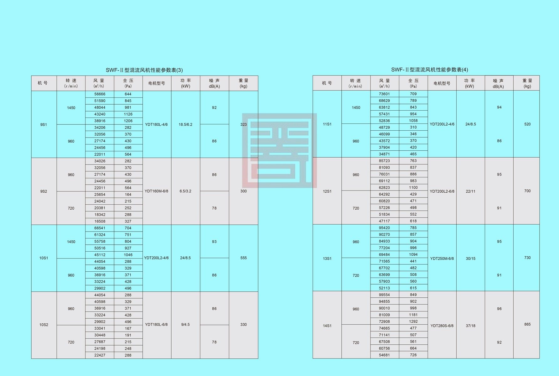
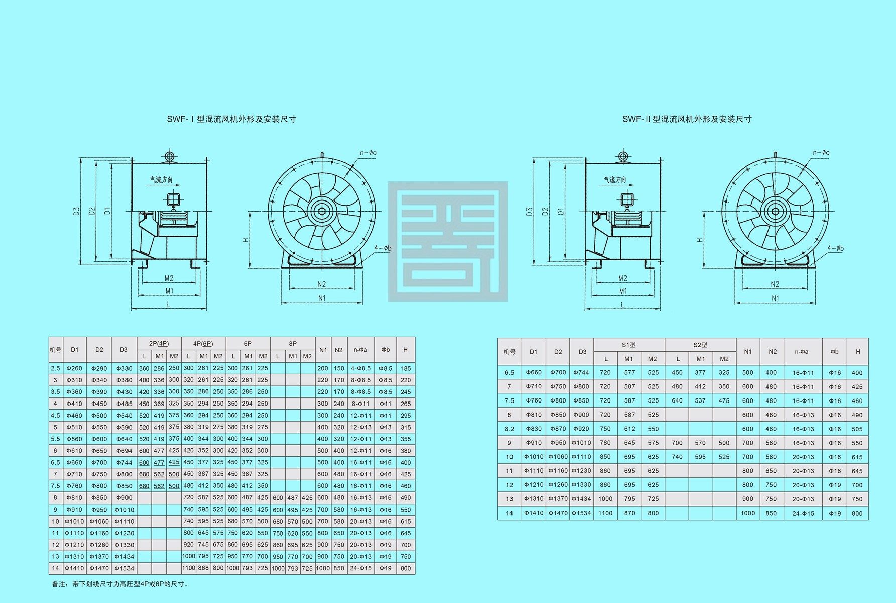
1.2 The fan series includes eighteen sizes ranging from 250 mm to 1400 mm. Air volume ranges from 500 m³/h to 110000 m³/h, and total pressure ranges from 50 Pa to 1400 Pa. According to speed‑regulation modes, fans are divided into single‑speed (Type Ⅰ) and two‑speed (Type Ⅱ). Two‑speed fans adopt dual‑speed motors for two‑gear speed regulation to meet performance adjustment requirements for different operating points. Variable‑frequency speed regulation is also available by pairing variable‑frequency motors with frequency controllers. The recommended operating frequency shall be locked within 25 Hz‑50 Hz.
1.3 Explosion‑proof versions are available for explosion‑hazard environments, with explosion‑proof grade Ex d Ⅱ BT4.
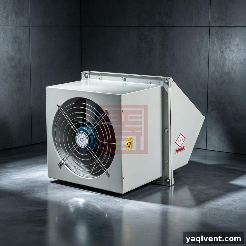
1.4 To satisfy noise requirements for various sites, silencers of different lengths can be equipped. The cladding‑type (casing noise‑reduction) structure is also optional.
2. Operating Conditions
‑ Operating temperature: ‑20 ℃ ~ +40 ℃ ‑ Relative humidity: <90 % ‑ Working medium: Air (dust content ≤ 100 mg/m³) ‑ Power supply: 3‑phase, 380 V / 50 Hz
3. Applications
The fan is widely used for ventilation and air exchange in civil buildings, industrial and mining enterprises, hotels, restaurants, museums, gymnasiums and other locations. It is particularly suitable for duct pressurization, air supply and exhaust, as well as ventilation for high‑rise and general buildings.
4. Configurations of SWF Mixed‑flow Fan
4.1 Standard Configuration
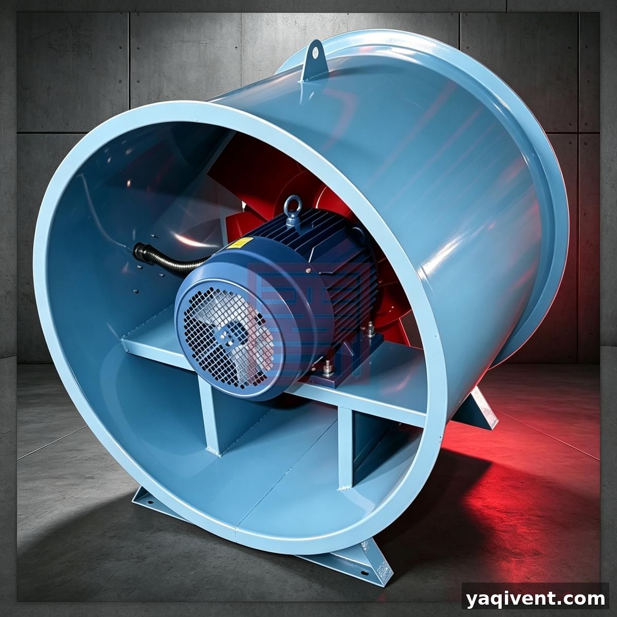
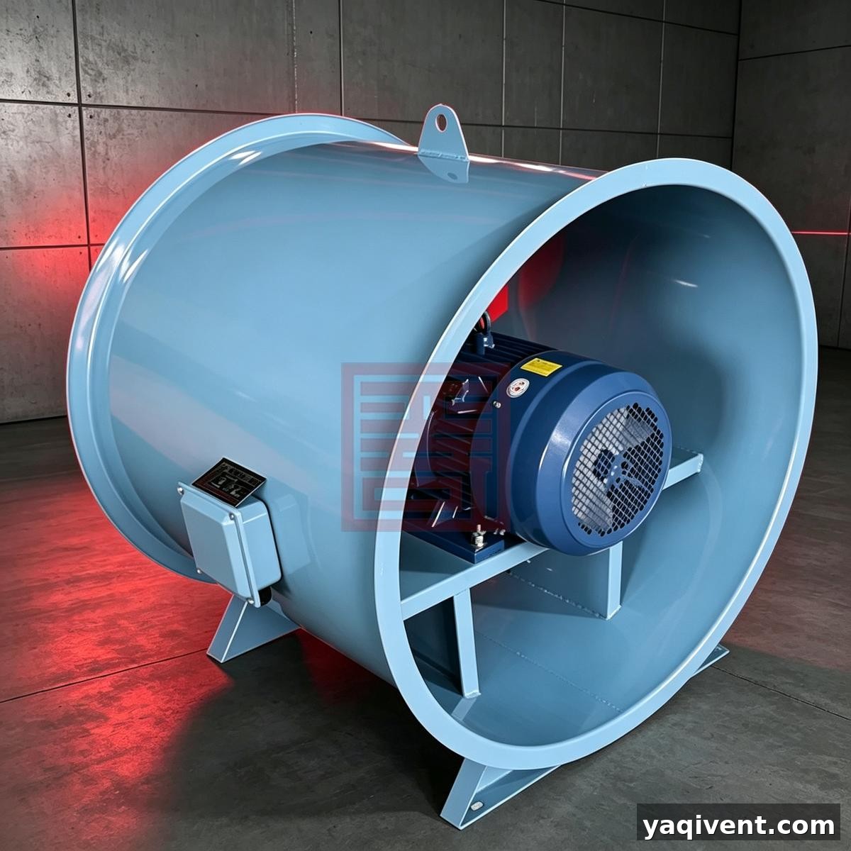
‑ Impeller ‑ Motor ‑ Casing (barrel, inlet nozzle, guide vane, inner barrel, motor support bracket) ‑ Base feet
4.2 Optional Accessories (Specify upon order placement)
‑ Vibration‑damping devices ‑ Control box ‑ Protective mesh guard ‑ Adapter flange
5. Manufacturing Process
5.1 The fan impeller is steel‑made. The hub is hydraulically drawn. Blades are stamped and hydraulically formed, then welded and assembled onto the hub. The impeller undergoes static and dynamic balance calibration with balance accuracy no higher than Grade G5.6.
5.2 The outer‑barrel flange is integrally formed by spinning‑flanging process. The inlet nozzle is hydraulically formed with dedicated dies.
Reviews
There are no reviews yet.