
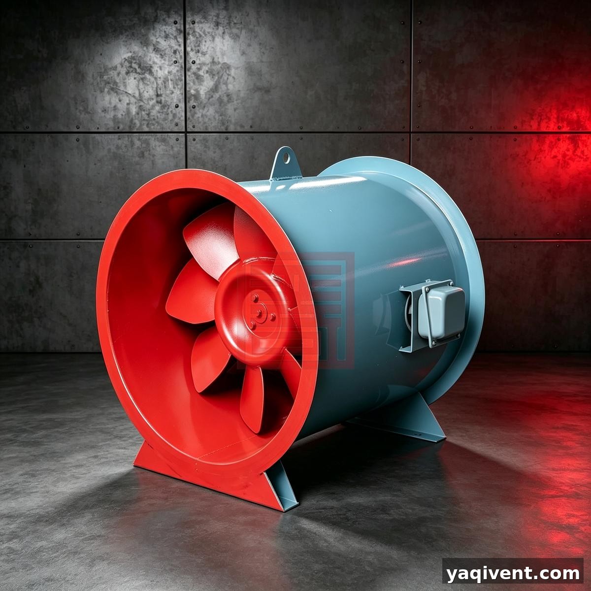
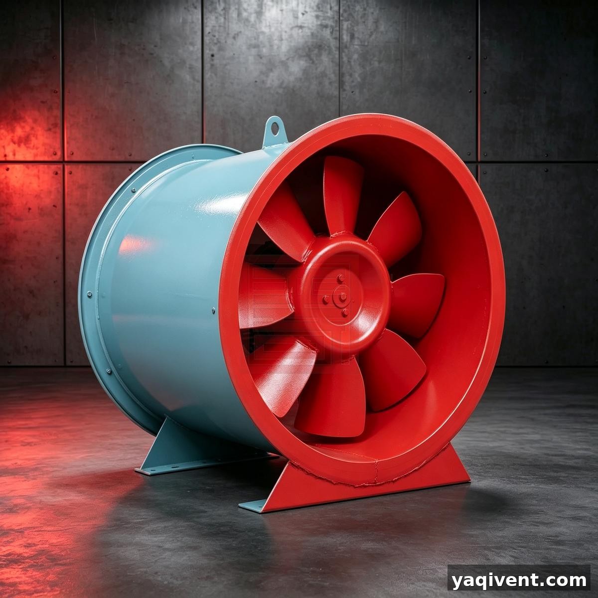
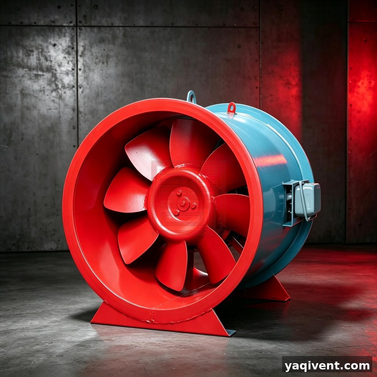
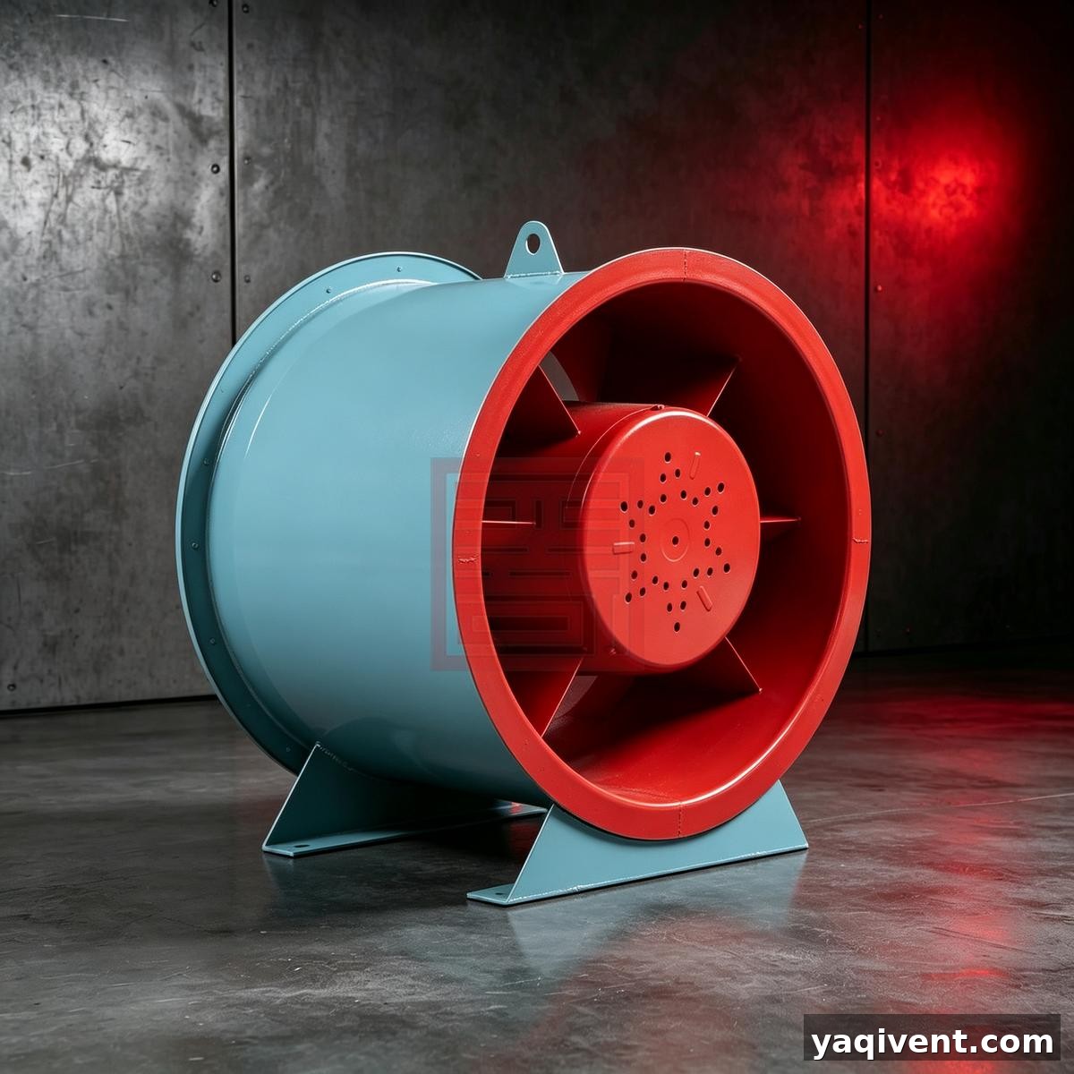
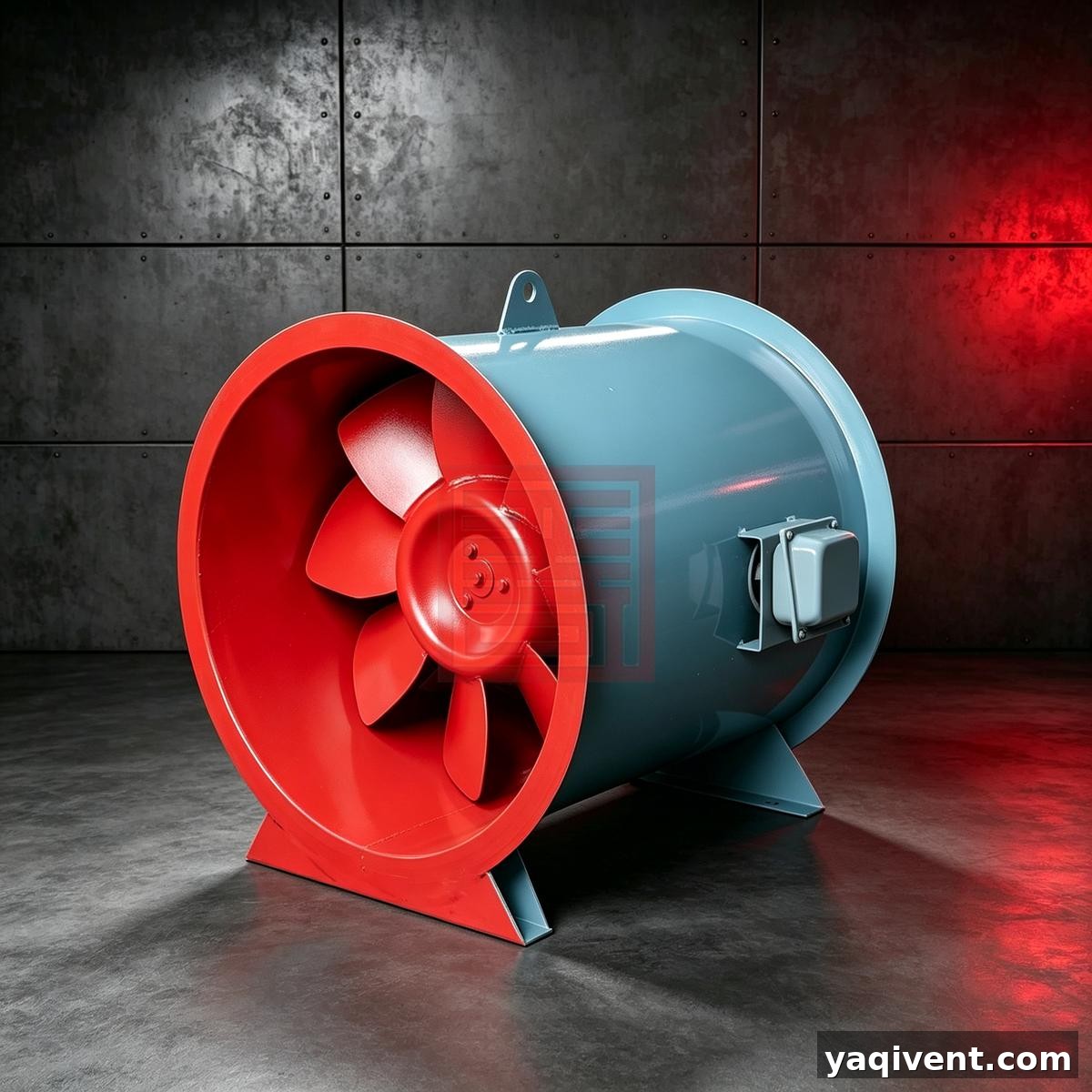
1. Overview of HTF Fire‑resistant High‑temperature Smoke‑exhaust Axial Fan
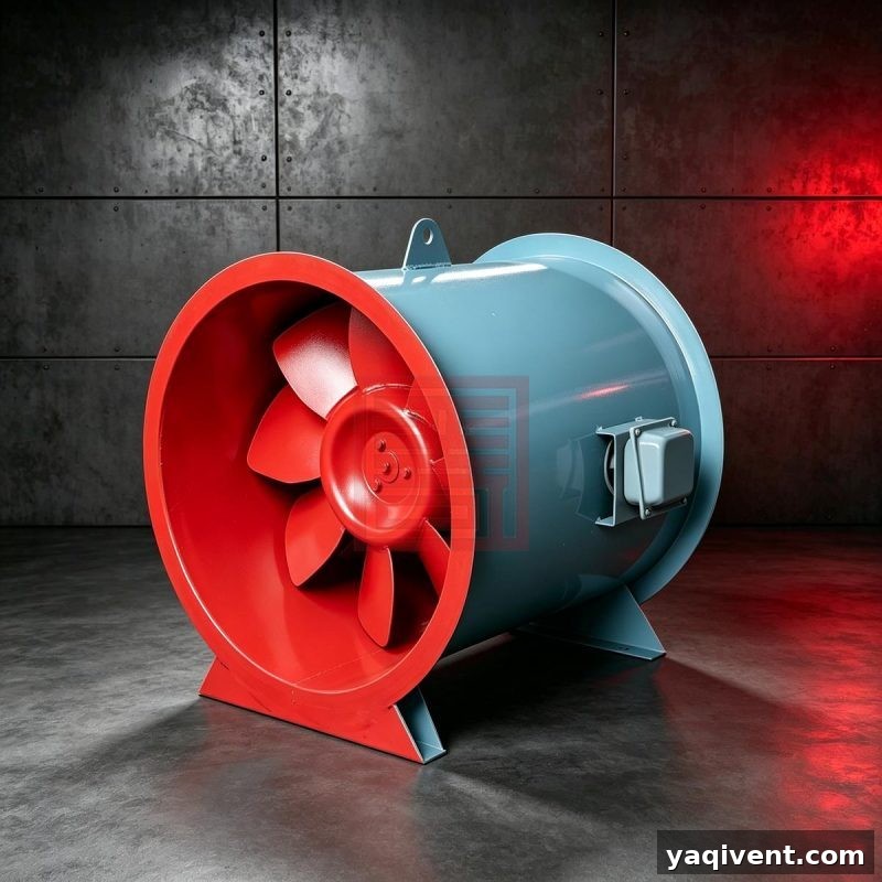
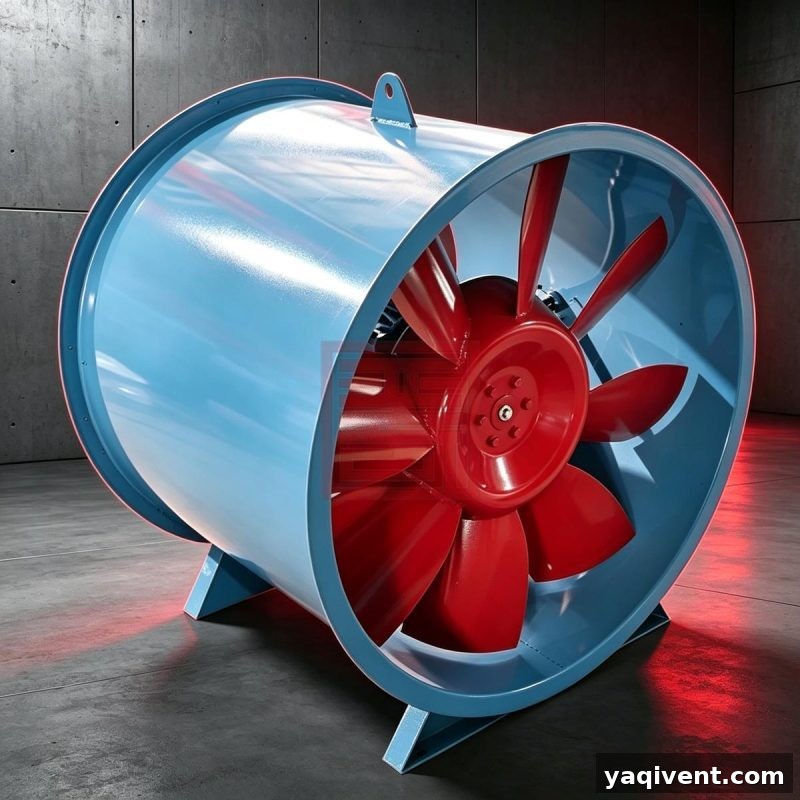
1.1 The HTF fire‑resistant high‑temperature smoke‑exhaust axial fan features a basic axial‑flow structure. It is equipped with a high‑temperature‑resistant motor and a dedicated motor cooling system. The product has passed the high‑temperature resistance test performed by the National Quality Supervision and Inspection Center for Fire‑fighting Equipment in accordance with GA211‑1999 Test Method for High‑temperature Resistance of Fire‑smoke Exhaust Fans. It can run continuously for more than 60 minutes at a medium temperature of 300 ℃, and operate continuously for 20 hours per cycle without damage at 100 ℃. The fan can be used for both ventilation and smoke exhaust.
1.2 Product Classification
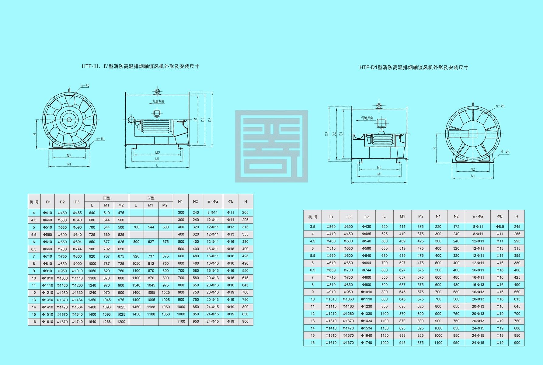
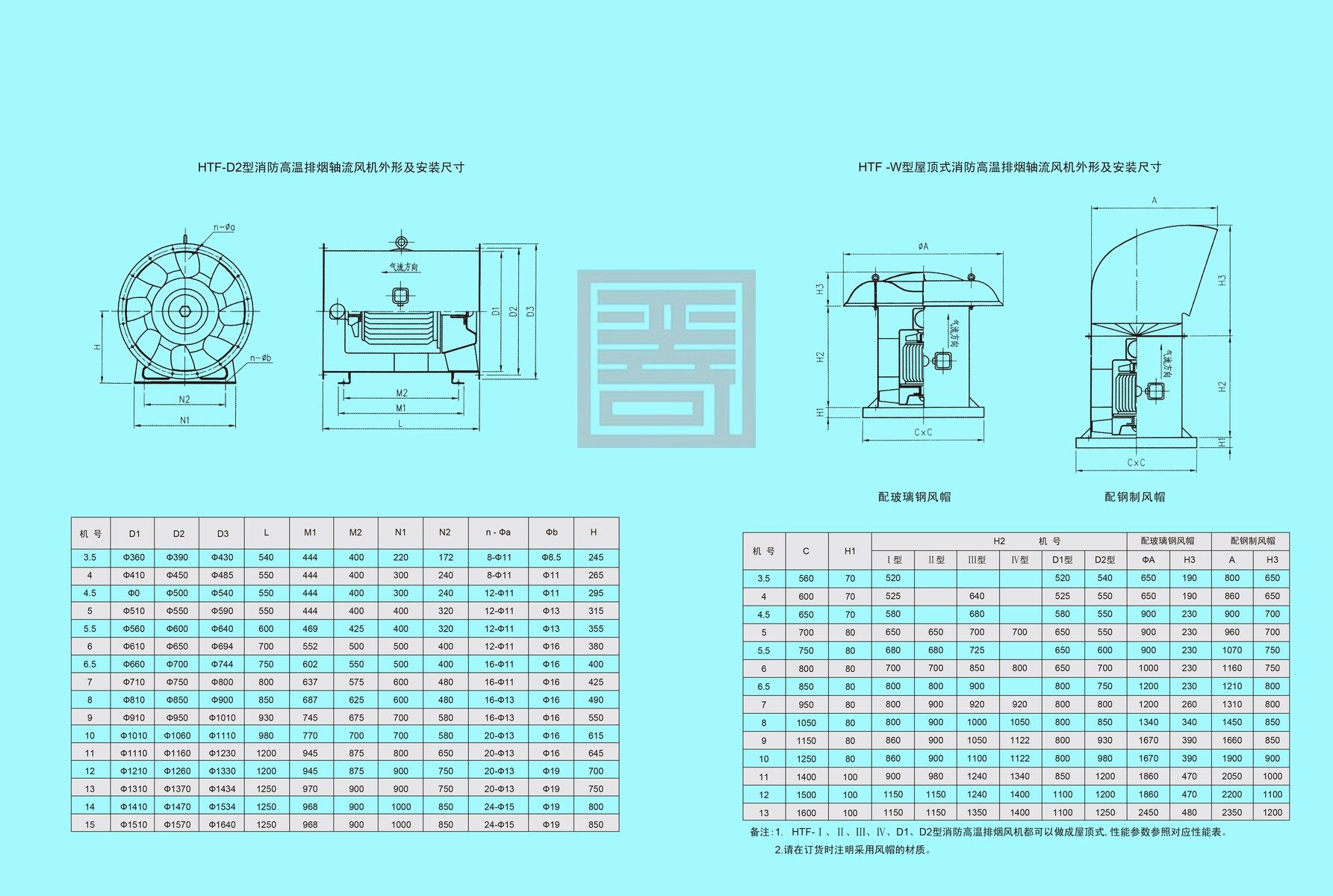
- By installation mode: Horizontal type and roof‑mounted type (Type W).
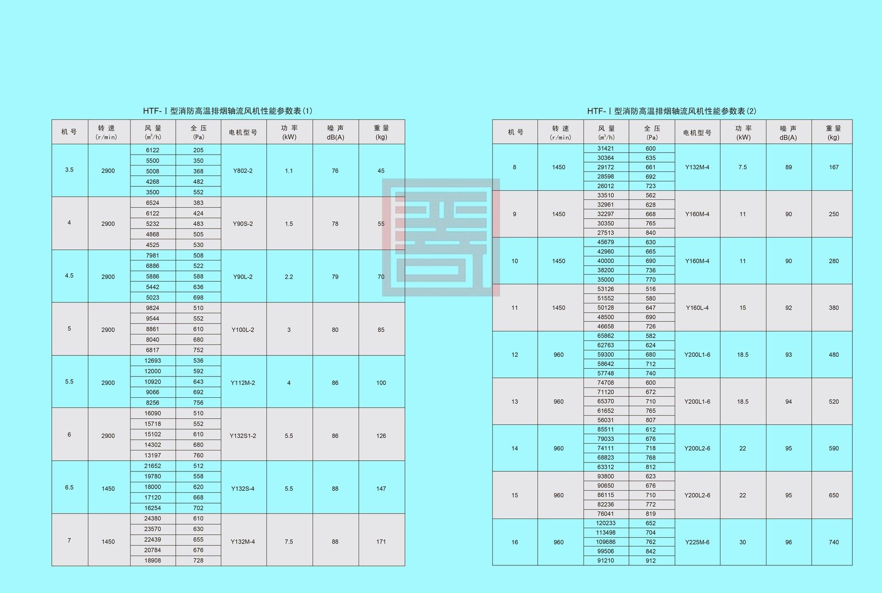
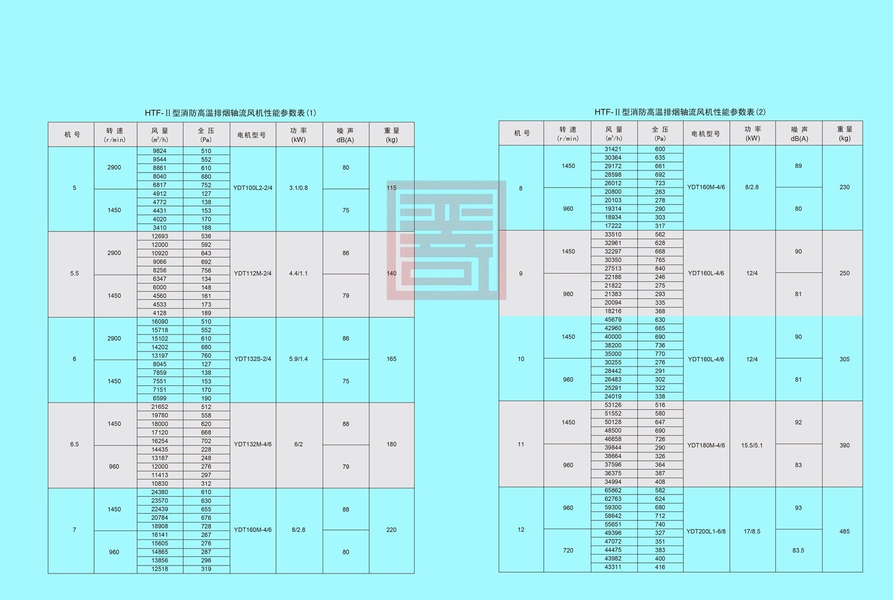
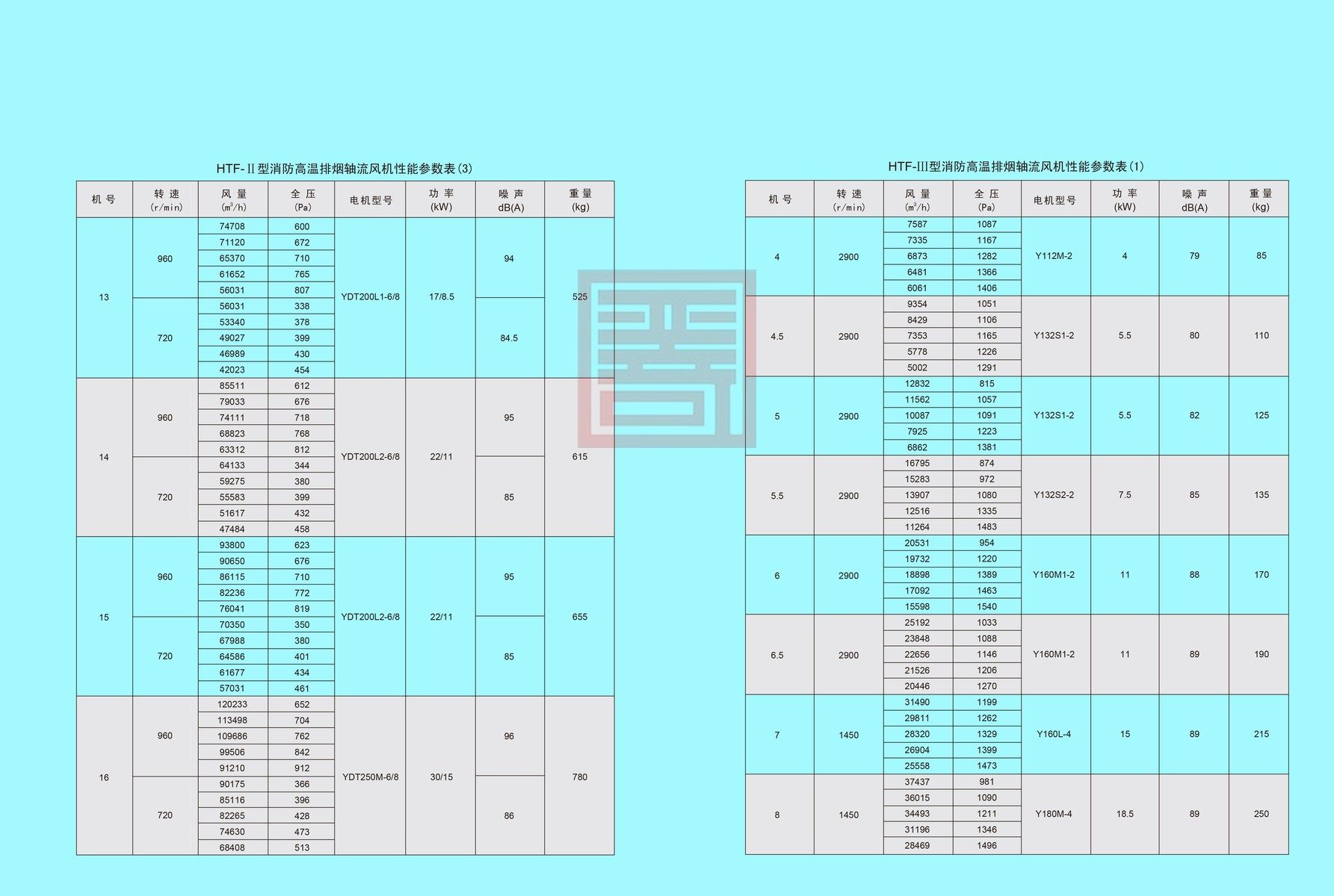
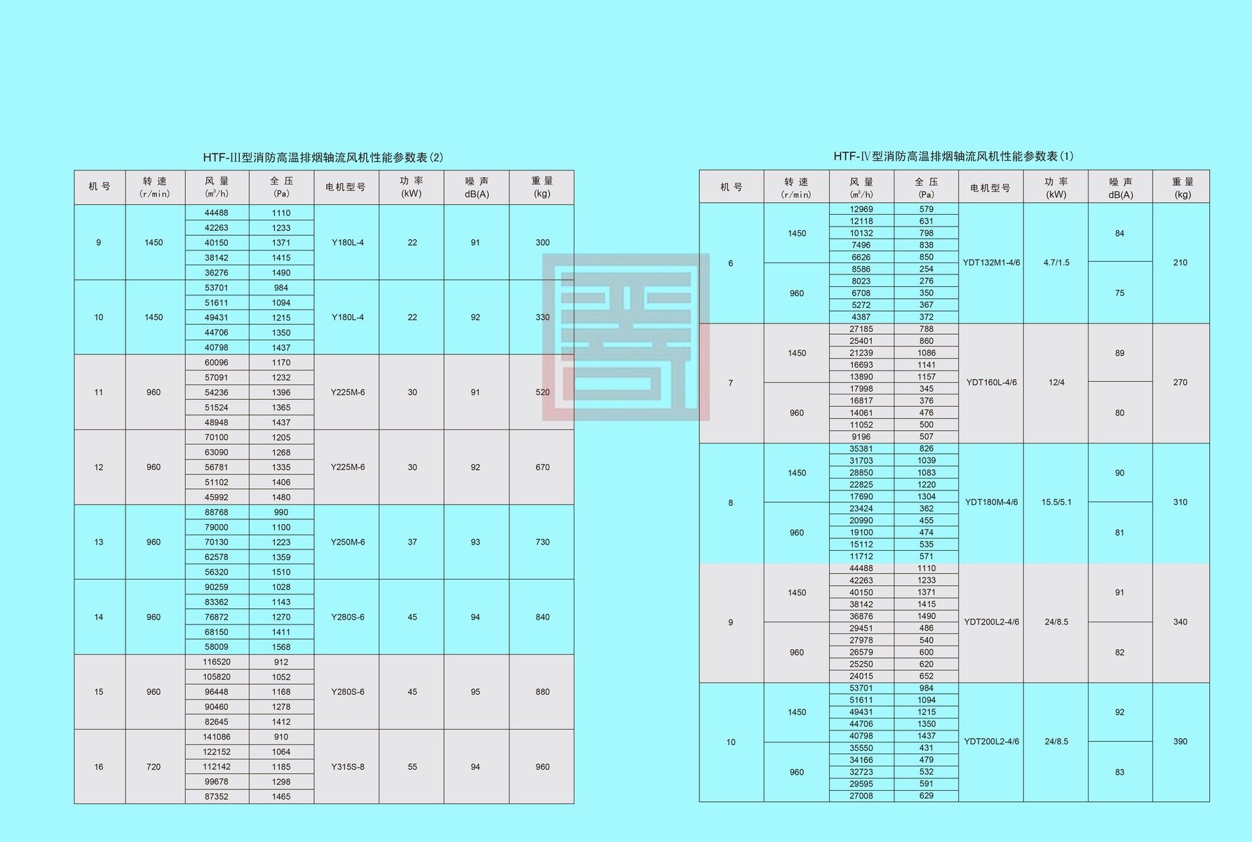
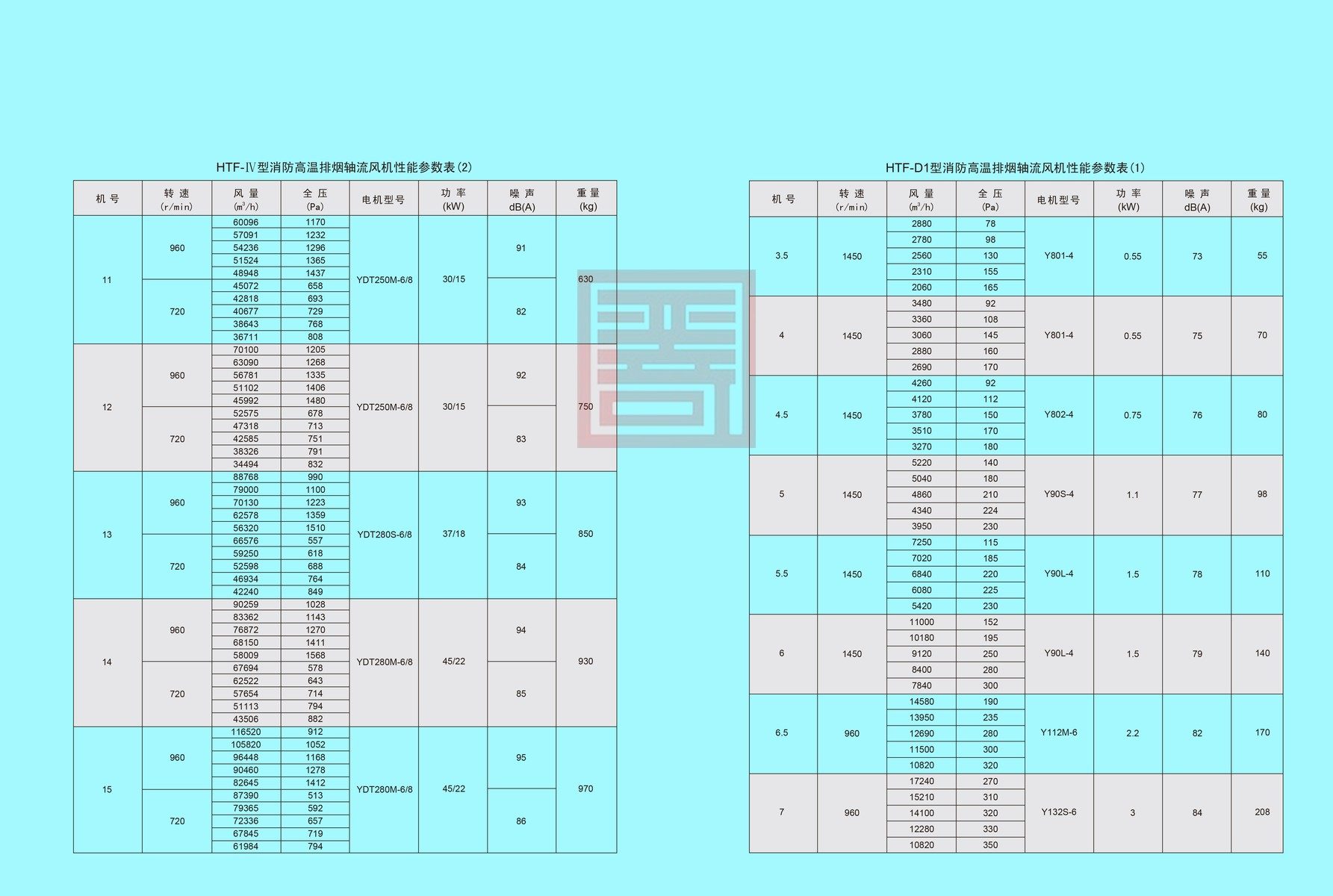
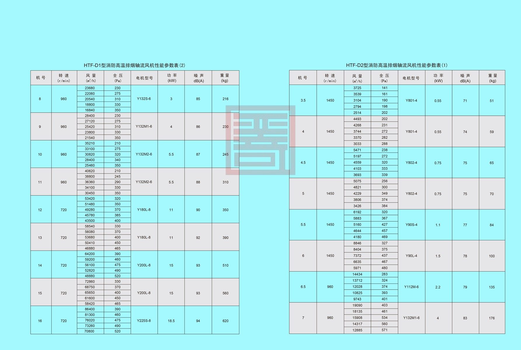
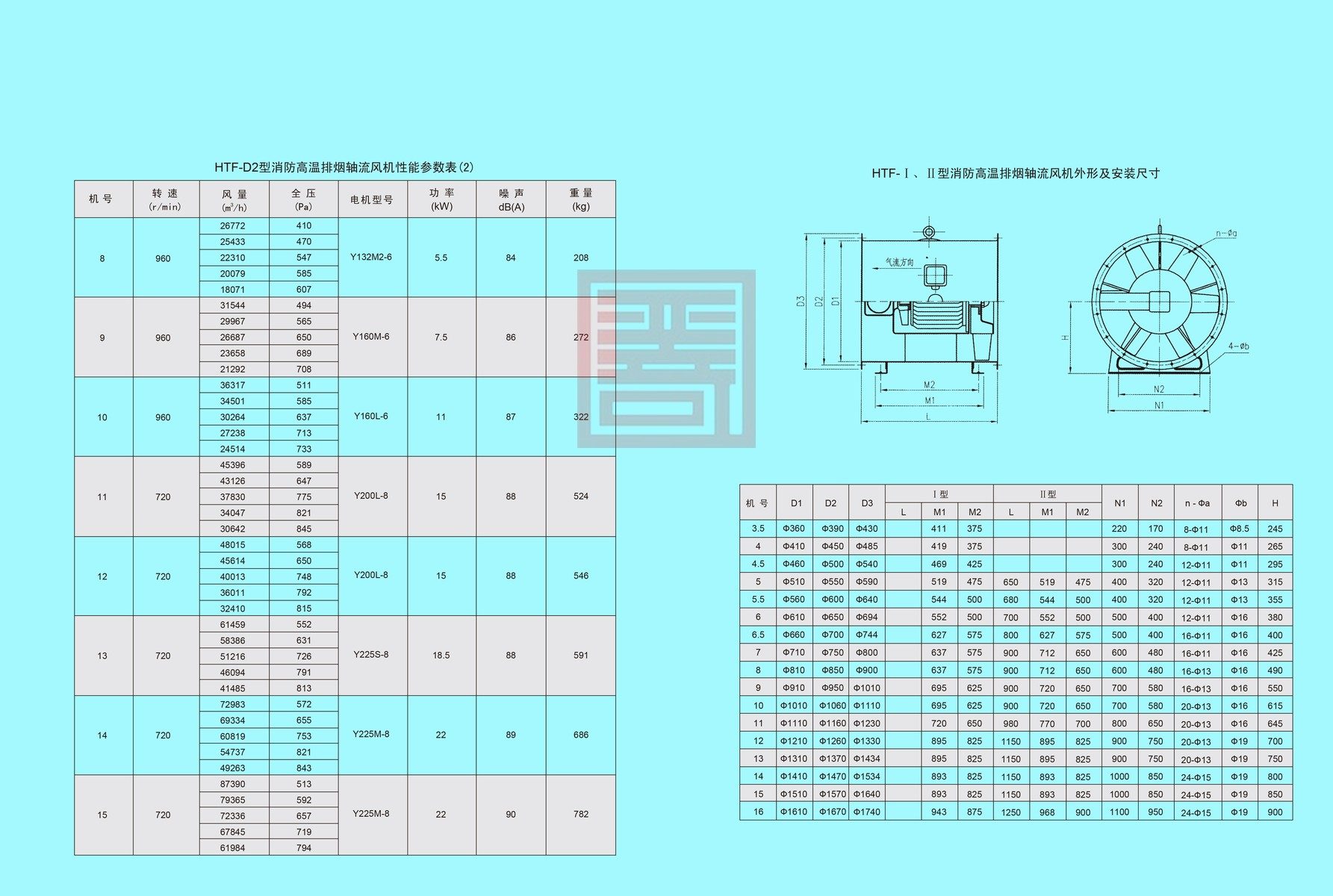
- By air volume & total pressure: Normal‑pressure type: Model Ⅰ, Model Ⅱ (two‑speed); Medium‑pressure type (with oblique‑flow impeller): Model Ⅲ, Model Ⅳ (two‑speed); Low‑pressure type: Model D1, Model D2.
- By speed‑regulation mode: Single‑speed, two‑speed, variable‑frequency. Variable‑frequency speed regulation is realized by adopting variable‑frequency motor matched with frequency converter to adapt to various working conditions. It is recommended to keep the operating frequency within 25 Hz‑50 Hz.
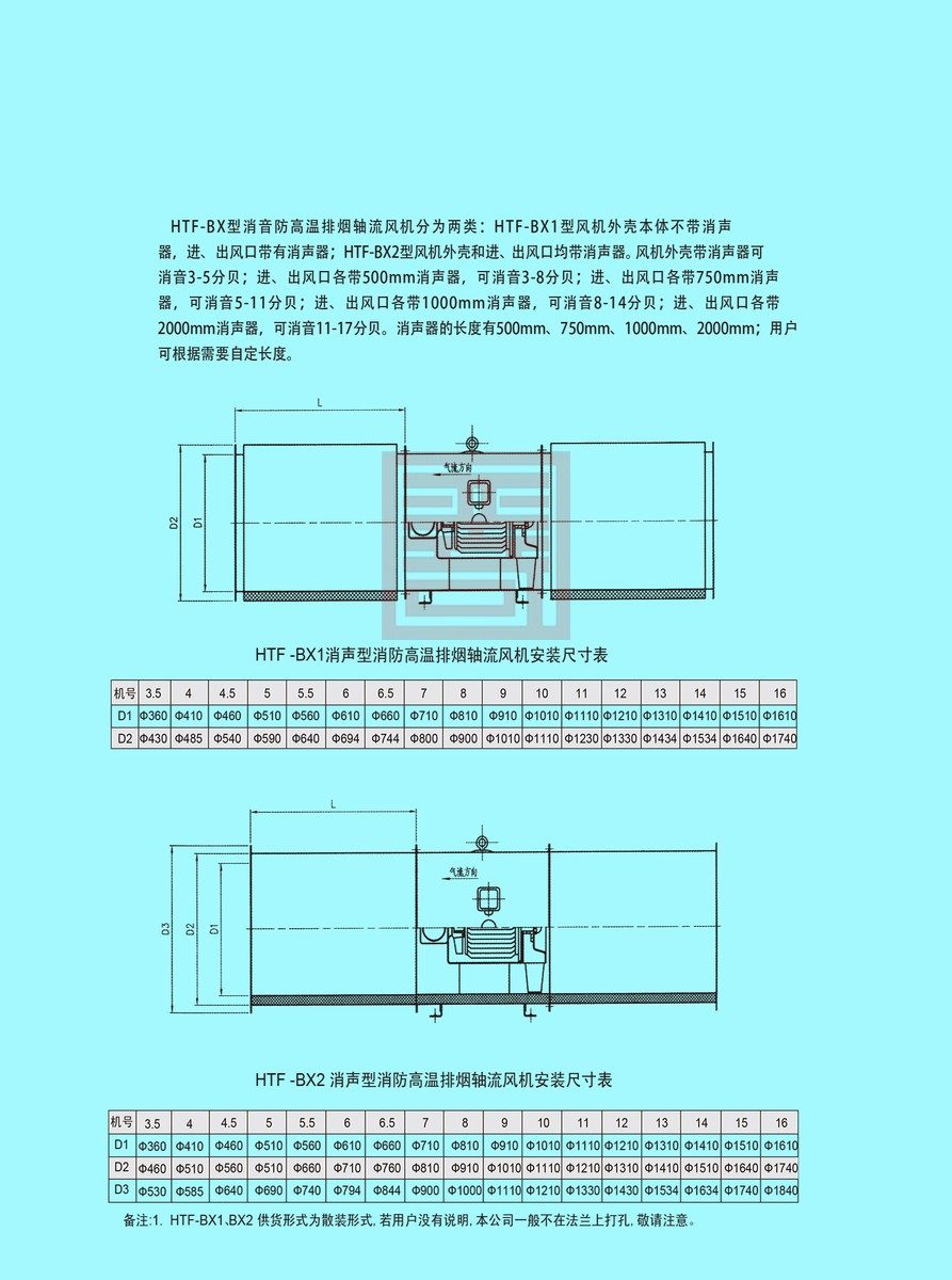
1.3 To satisfy noise requirements of different sites, silencers of various lengths can be equipped for the fan. The cladding type (casing noise‑reduction) is also available.
2. Operating Conditions
- Continuous operating temperature: ‑20 ℃ ~ +60 ℃
- High‑temperature resistance: 100 ℃ (continuous operation for 20 hours); 300 ℃ (continuous operation for 60 minutes)
- Relative humidity: <90 %
- Working medium: Air (dust content ≤100 mg/m³)
- Power supply: 3‑phase, 380 V / 50 Hz
3. Applications
The fan is widely applied for ventilation and smoke exhaust in high‑rise buildings, ovens, underground garages, tunnels and other locations.
4. Configurations
4.1 Standard Configuration
‑ Impeller ‑ Casing (barrel, guide vane, inner barrel, motor support bracket) ‑ Motor ‑ Cooling impeller ‑ Base feet ‑ Cooling air duct
4.2 Optional Accessories (Specify upon order placement)
‑ Vibration‑damping devices ‑ Control box ‑ Protective mesh guard ‑ Adapter flange
5. Manufacturing Process
5.1 The fan impeller is made of steel. The hub is formed by hydraulic drawing. Blades are stamped and hydraulically shaped, then welded and assembled onto the hub. The impeller undergoes static and dynamic balance calibration with balance accuracy not higher than Grade G5.6.
5.2 The outer‑barrel flange is integrally formed by spinning & flanging process.
Reviews
There are no reviews yet.